
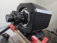
Intro
Besides working in IT every day on things like Kubernetes, I also really enjoy building physical things and being busy with my hands. For a while I had been following some sim racing subreddits and I wanted to get into it myself. Patriek also has his own sim rig, and that made me even more curious to get started with it. My goal: cheap but good. Not something that always goes hand in hand.
In the summer I came across the FFBeast project and a YouTube video of the DAZ DIY racing wheel. I was sold on the idea straight away and bought a hoverboard on Marktplaats for 20 euros. With FFBeast you can build a wheel base up to 12Nm, which normally costs around 450 to 600 euros for just the base, without a wheel.
FFBeast uses the hub motor of a hoverboard as a direct drive wheel base, together with a motor controller running the FFBeast firmware and a magnetic encoder that reads the position of the wheel.
My build requirements
- A quick release adapter
- USB passthrough through the wheel, so no loose cables to connect the wheel
- 3D printed as much as possible
- A professional look
My idea
In the motor enclosure I wanted to build in a USB hub, where one USB port goes to the motor controller and the other one goes to a slip ring to connect the wheel through USB. A slip ring passes signals from a part that stands still to a part that rotates, so the USB connection keeps working while the wheel turns without the cable twisting around the shaft. On AliExpress I found a quick release with 5 copper pads. The idea was to cut the connections between these pads with a Dremel and make 5 individual pads out of them, so you can connect a USB cable (4 wires) to it.

The quick release from AliExpress with the copper pads
Hardware
- Quick release adapter
- ODESC V4.2 High-precision Brushless Servo Motor Controller
- MT6701 magnetic encoder for the position of the wheel
- USB hub
- XT60 connectors
- USB-C female connector
- Slip ring
- 10x2mm magnets to attach the panels to the enclosure
- 350W 24V power supply (Meanwell LRS-350 is the best choice but there are cheaper alternatives)
- 2040 extrusion profile
- 70mm wheel spacer for a longer wheel shaft
- 2 SK16 mounts for mounting the motor to the base
In total the wheel base cost me around 180 euros.
Phase 1: Drilling the stator
This was the hardest part of the whole project, because here it is all about precision. A hole has to be drilled through the middle of the stator to guide the encoder and the other wiring through it. This hole has to be exactly in the middle and go straight down. If the encoder is not aligned properly, the FFBeast will not work well.
First I took the hoverboard apart. Then I drilled a 10mm hole for the encoder holder and the slip ring for the USB passthrough. I did this step by step, going up one drill size at a time. The core is hardened steel, so it is hard to drill through.

Drilling the hole through the hardened steel core of the stator
Phase 2: Making 5 individual pads on the quick release PCB
With a multimeter I figured out which pads were connected to what, so I could find the traces on the PCB. Then I cut these traces with a Dremel, which gave me 5 individual pads. After that I connected the slip ring wiring to the pads and used the continuity mode of the multimeter to check if every wire made contact and if there was no short circuit anywhere.
Later on I also designed a proper PCB for this, more about that at the end.

The quick release PCB after cutting the traces with the Dremel
Phase 3: Designing the case
I designed the case in Fusion 360. Online I found several CAD models, for example of the hoverboard motor and the encoder. This way I could place the models on the 2040 extrusion, which gave me a clear template to design around. I used the magnets to mount the front and back plate of the wheel base enclosure. This way you don't need an Allen key or a screwdriver and you can remove the enclosure within seconds.

The enclosure designed in Fusion 360
Phase 4: Building it
First the firmware has to be flashed on the ODESC. This is described well on the FFBeast website and in their Discord channel.
When all parts were printed, I glued the encoder holder into the stator with epoxy. Then I soldered the encoder and guided its wiring together with the slip ring wiring through the stator. After that the slip ring wiring got a USB-A connector on one side, and the encoder wiring was connected to a JST connector for the ODESC controller.
The other side of the slip ring is connected to the PCB of the quick release, where I made the 5 individual contact pads. In my case the outer ring was 5V, the inner ring GND and the two middle ones D+ and D-. On the wheel side I connected the pogo pins in the same way. The pogo pins press against the PCB of the wheel base and that way they make contact.
Finally I connected the wiring to the PSU and soldered an XT60 male and female connector on the wheel base and the PSU.

The encoder holder fitted in the stator

Soldering the encoder
Phase 5: Testing
For the wiring of the ODESC I followed the connection guide in the FFBeast docs.
After everything is connected, it is time to connect it to your PC. In the FFBeast software you can set the power limit for the wheel and for example the rotation angle. After that I tested it in game and it works really well! So if you see me online in Le Mans Ultimate, watch out at Monza T1, because it won't be safe there for a while.
At the moment I'm running it at 80% of the power limit with a rotation angle of 480 degrees. For me that is more than enough power.
Conclusion
It was a very educational and fun project. I really liked seeing something I designed in 3D turn into a physical thing. In the meantime I also made two fully 3D printed wheels, which can be connected to the wheel base easily with the quick release, just like the real thing.
The latest version of the wheel also has RGB lighting built in. With a program called SimHub this lighting can be controlled with telemetry data from the game itself. This way the LEDs work as a rev counter, but can also be used for things like yellow or blue flags. It's actually a bit useless since I race in VR, but RGB LEDs are always cool, so why not.
Recently I also designed my own PCB in KiCad to replace the quick release PCB with the contact pads I made with the Dremel, and had it produced. I still need to put it on the wheelbase, so that is the next step.
Right now the wheel base is mounted on a GT Lite. I bought it earlier because it's easy to store away, but since I like this so much I'm thinking about building a fixed rig, and making that myself as well.

The PCB design in KiCad, with the pinout on the board

My own PCB designed in KiCad: the contact rings on the front

The back of the PCB with the connector and pinout
If you liked this post, let me know and I'll also write one about building the steering wheel itself.

A sneak peek of the steering wheel